Keeping O2 Sensors Working Their Best
The oxygen sensor, commonly referred to as the O2 sensor, is a workhorse component of the emission control system in the modern vehicle. This device is now used in pairs at the entrance and exit ends of the catalytic converter. It senses the amount of oxygen in the exhaust stream. That oxygen content data is used to constantly adjust the air/fuel ratio in order to maximize fuel economy, optimize performance and minimize tailpipe emissions.
Early O2 sensor designs were somewhat unreliable and service life could be decreased by factors like using poor quality gasoline. Over the years, though, reliability and performance has increased significantly. Now, service life of this component may exceed 100,000 miles.
Oxygen Sensor Basics
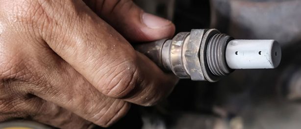
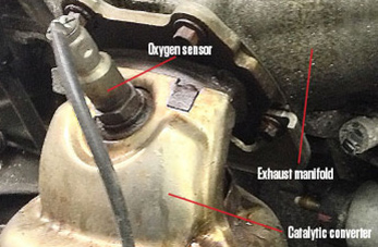 The O2 sensors play a critical role in the control of exhaust emissions. They are located in the exhaust path, with one sensor on the inlet side of the converter and the other on the exhaust end. The image on the left shows an O2 sensor on the inlet side of a 3.6L V6 engine, which is used extensively throughout the FCA US LLC vehicle lines.
Once the O2 sensor reaches operating temperatures between 572◦ and 662◦F, the sensor generates a voltage that is inversely proportional to the amount of oxygen in the exhaust. In other words, if the voltage is low, oxygen content in the exhaust is high, and vice versa. The oxygen content information obtained by the sensor is used to calculate the fuel injector pulse width (the amount of time the injector is on). The PCM is programmed to maintain the optimum air/fuel (A/F) ratio. At this mixture ratio, the catalyst works to remove hydrocarbons (HC), carbon monoxide (CO) and nitrides of oxygen (NOx) from the exhaust stream.
In the early days of O2 sensor use, a period of time had to elapse before the sensor reached operating temperature. The only thing heating the O2 sensor was the exhaust stream. Depending on the distance from the exhaust manifold to the converter, some of the exhaust heat was lost. Keep in mind that the voltage readings taken from the O2 sensor are very temperature-sensitive and usually not accurate below 572◦F.
Solving this problem was simple – they created a heater for the sensor. O2 sensors are now equipped with a heating element to bring it up to temperature fast. The net result is the ability of the engine controller to shift to closed loop operation as soon as possible. As part of the onboard diagnostic system, the heating element is tested to ensure that it is heating the sensor properly.
O2 Sensors and Catalytic Converters
The catalytic converter monitor uses dual O2 sensors to monitor the efficiency of the converter. The dual O2 sensors strategy is based on the fact that as a catalyst deteriorates, its oxygen storage capacity and its efficiency are both reduced. By monitoring the oxygen storage capacity of a catalyst, its efficiency can be indirectly calculated.
The upstream O2 sensor is used to detect the amount of oxygen in the exhaust gas before the gas enters the catalytic converter. The PCM calculates the A/F mixture from the output of the O2 sensor. A low voltage indicates high oxygen content (lean mixture). A high voltage indicates a low content of oxygen (rich mixture).
O2 Sensor Problems
As an O2 sensor deteriorates over time, the driver of the vehicle, in the vast majority of cases, is not going to notice any real change in vehicle performance. Sure, fuel economy might slip a bit, but how many people are going to notice that? If the heating element fails, the time to reach closed loop operation will take a bit longer. What the driver will notice is an illuminated check engine light or MIL (malfunction indicator lamp). Diagnostic Trouble Codes (DTCs) will be set if a problem occurs with one of the O2 sensors or the heater element.
The O2 sensor can fail in any or all of the following manners:
- Slow response rate
- Reduced output voltage
- Dynamic shift
- Shorted or open circuits
Response rate is the time required for the sensor to switch from lean to rich once it’s exposed to a richer-than-optimum A/F mixture (or vice versa). As the sensor starts malfunctioning, it could take longer to detect the changes in the oxygen content of the exhaust gas.
The output voltage of the O2 sensor ranges from 0 to 1 volt. A good sensor can easily generate any output voltage in this range as it is exposed to different concentrations of oxygen. To detect a shift in the A/F mixture (lean or rich), the output voltage has to change beyond a threshold value. A malfunctioning sensor could have difficulty changing beyond the threshold value.
Diagnostic Trouble Codes
The service information for a particular vehicle will list the various DTCs along with the diagnostic procedures. In general, the codes for issues with the heater circuits are P0031, 32, 37, 38, 51, 52, 57 and 58. A more extensive list of DTCs covers issues with inactive signals, slow response, heater performance and circuit low/high. These DTCs are P0131 through P0161 (not every number is used in this sequence). Follow the diagnostic procedures for the particular code to determine the course of corrective action.
You will note that each DTC references a specific O2 sensor. For example, DTC P0153-02 Sensor 2/1 Slow Response refers to sensor 2/1. Remember, there are 4 O2 sensors. The sensors are identified as follows:
- 1/1 Right Upstream Sensor
- 1/2 Right Downstream Sensor
- 2/1 Left Upstream Sensor
- 2/2 Left Downstream Sensor
So, in the example DTC, the O2 sensor in question is the left upstream sensor.
O2 Sensor Replacement (3.6L V6 Engine)
Disconnect the negative battery cable. Raise the vehicle (if necessary to gain access). Always allow the engine to cool before removing the O2 sensor as exhaust pipes and catalytic converters can become very hot during engine operation.
Disconnect the heated O2 sensor electrical connector. Do not pull directly on the wire going into the sensor as the sensor wiring can be damaged if this is done, resulting in sensor failure.
Remove the O2 sensor. Clean the exhaust pipe threads using the appropriate tap.
If the original O2 sensor is being re-installed, coat the sensor threads with an anti-seize compound such as Loctite 771-64, or equivalent. New sensors have compound applied to the threads and do not require additional coating. Do not apply additional anti-seize compound to the threads of a new O2 sensor.
Install the new O2 sensor. Tighten it to 32 lb.-ft., except for the left downstream sensor. Tighten it to 33 lb.-ft. Connect the heated O2 sensor electrical connector. Lower the vehicle. Connect the negative battery cable to complete the job.
0 Comments