
Fuel for Thought
How to Deal with Dirty, Clogged, Leaky or Electrically Challenged Fuel Injectors
Fuel Injection Basics
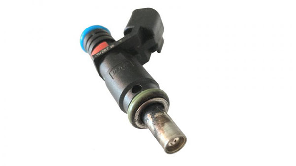
A fuel injector is a 12-volt electrical solenoid (see Figure 1); a rather simple electro-mechanical device but one with tight clearances and tolerances. The injector contains a pintle that closes off an orifice at the nozzle end of the injector. When electric current is supplied to the injector, the injector’s armature and needle move a short distance against a spring, allowing fuel to flow out of the orifice. Because the fuel is under high pressure, it exits the nozzle atomized and blending with air as it enters the combustion chamber.
The engine’s powertrain control module (PCM) fires the injectors in a specific sequence and maintains – through constant adjustment of the injector pulse width (the length of time the injector is open) – an ideal air/fuel ratio of 14.7 parts air to one part fuel. The PCM adjusts injector pulse width by opening and closing the ground path to the injector.
When a fuel-injected engine is at operating temperature, it is in Closed Loop mode. In this mode, the following inputs provide data to the PCM to allow it to constantly adjust the pulse width:
- A/C switch status
- Camshaft position
- Crankshaft position (engine speed)
- Engine coolant temperature
- Exhaust gas oxygen content (O2 sensors)
- Inlet/intake air temperature
- Knock sensor
- Manifold absolute pressure
- Throttle position
- Vehicle speed
With fuel injection, pulse width adjusts for every engine stroke, providing precise fuel control. Early fuel injectors injected the fuel outside of the combustion chamber by the base of the intake valve. As the valve opened, the fuel was mixed with the incoming air as it flowed into the combustion chamber. Modern-day fuel injectors fit into the combustion chamber wall, directly injecting fuel into the cylinder; thus, the term “direct injection”.
Fuel Injector Problems
Fuel injector problems might not be obvious to the driver of the vehicle. If the injectors are dirty, limiting fuel flow, the decline in performance is progressive and, at times, unnoticeable. In other instances, an electrical or mechanical failure can occur, resulting in a more noticeable decline in performance. Regardless of the source of the problem, a diagnostic trouble code (DTC) will be set and the malfunction indicator lamp (MIL) or the check engine light will be illuminated. Once that occurs, the driver should seek help from a professional.
Dirt can, and will, inhibit fuel injector performance. The best way to prevent dirt-related problems is to use top-tier gasoline, change the air filter element on a regular basis and, as an added measure, add fuel injector cleaner once a year to the gas tank.
Clogged or Leaking Fuel Injector
An engine misfire will usually set a DTC in the memory of the PCM – code P030# with the last digit indicating the cylinder in which the misfire occurred.
Misfires occur for a number of reasons, including a clogged injector. To determine if the injector is the cause, eliminate the other causes of engine misfire, which include vacuum leaks, a bad coil, a bad spark plug or a leaking head gasket. Once the other causes have been eliminated, you can concentrate on checking the fuel injector.
Fuel Injector Circuit Problems
Typically, when a fuel injector fails, there is a problem with the fuel injector circuit – the pintle is not opening to allow fuel to spray into the combustion chamber. The DTC for this condition is P020#, in which the last digit denotes the cylinder number. This code is set when any circuit fault reduces the maximum current flow or the magnitude of the voltage spike.
After the DTC has been verified, make sure the connector is properly connected to the fuel injector. If it is, disconnect the connector and closely inspect the wiring and terminals, looking for causes of a poor connection – chafed, pierced, pinched or partially broken wires, as well as broken, bent, pushed out or corroded terminals.
If those items are okay, use a 12-volt test light connected to ground, and probe the Fused ASD Relay Output (F342) circuit. Turn the ignition on. The test light should illuminate brightly. If the test light does not illuminate brightly, repair the ASD relay output circuit.
Next, turn the ignition off. Disconnect the PCM C2 harness connector. Check for continuity between ground and the (K11) Injector 1 control circuit at the fuel injector harness connector. Remember, if the suspected problem is with another cylinder (for example, #4), check the Injector 4 control circuit. There should be no continuity between these two points. If there is continuity, repair the K11 circuit for a short to ground.
Now, connect the GPEC Diagnostic Adapter (P/N 10436) and check the (K11) Injector 1 control circuit for an open or high resistance. Measure the resistance of the control circuit between the harness connector and the GPEC Adaptor. The resistance should be below 3.0 ohms. If the resistance is greater than 3.0 ohms, check the circuit for an open or high resistance.
Finally, check the resistance of the fuel injector. Remember, the resistance varies based on the temperature of the injector coil (refer to the service manual of the vehicle being repaired for a table listing coil temperatures and resistance). If the resistance of the fuel injector is not within the specified range, it is bad and must be replaced.
0 Comments